Imperial Stud
Imperial Stud

(a) stud threaded each end without recess

(b) stud threaded each end with recess to lock on thread runout

(c) stud threaded each end with recess to lock against bottom of hole
Studs
General
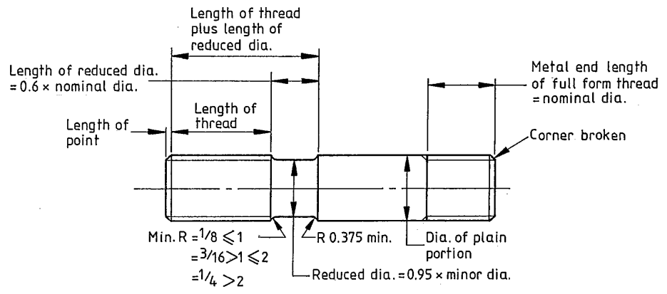
The forms of the studbolts shall comply with those shown in figure 5(a),
(b),
(c) or (d). Studs to figure 5(a) shall comply with BS 2693 : Part 1, covering sizes up to 1 1/2 in
nomial diameter. Pitch details shall comply with 3.2.10.
The dimensions of studs to figure
5(b) shall be as given in 3.2.2 to 3.2.10 and tables 16 to 17 and 19 for studbolts.
Nominal length
The nominal length shall be in the following increments:
(a) increments of 1⁄8 in for lengths up to and including 5 in;
(b) increments of ¼ in for lengths above in.
NOTE. Nominal length excludes length of point (see 1.3.3.1).
The tolerance on nomial length shall be as given in table 17.
Length of metal end of thread
For studbolts to figures 5(b) the length of full form thread at
the metal end shall be the nomial
diameter except
where high strength studs are used with weak flange materials in which case
the
metal end threaded length shall be equal to 1.5 times the nominal diameter.
Length of nut end of thread
For studs as shown in figure 5(b) the basic length of thread shall be as given in table 20.
| Table 20. Length of thread for studs: inch series | |
|---|---|
| Nominal diameter | Thread Length |
| in | in |
| ≤ ⅞ | Nomial dia. + ¼ |
| > ⅞ ≤ 2¼ | Nomial dia. + 5/16 |
| > 2¼ ≤ 4 | Nomial dia. + 3⁄8 |
Length of reduced diameter portion
The basic length of the reduced diamter portion shall be 0.6 times the nominal diamter(see figure 5(b)),
and shall be rounded up to the next 1/16in.
The following tolerances shall apply to this dimension:
(a) ± 0.030, --0 in for lengths up to and including for lengths up to and including 1 1/8 in;
(b) ± 0.060, --0 in for lengths over 1 1/8 in;
length of thread plus length of reduced diamtere portion
The following tolerances shall apply to this dimension:
(a) ± 0.030 in for lengths up to and including 2 in;
(b) ± 0.060 in for lengths over 2 in and up to and including 6 in.
Ends
The nuts ends shall be finished with a point having an included angle of approximately 90° to a depth
slightly exceeding the depth of thread. Lengths of points shall be as given in table 19.
The metal ends shall be finished as follows:
(a) for studs as illustrated in figure 5(b) the corner shall be broken at 450 to give a smooth
edge;
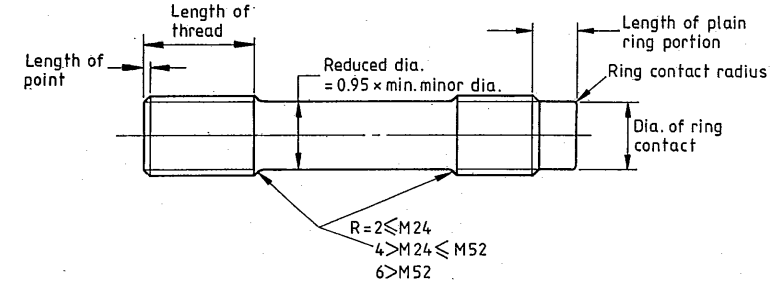
(b) for studs as illustrated in figure 5(b) the end dimensions shall comply with the scale of sixes gven the
table 21.
| Table 21. Stud dimensions: inch series | ||
|---|---|---|
| Nominal diameter | Ring contact diameter | Length of plain ring portion |
| in | in | in |
| ≤ ⅛ | Nomial dia. + ¼ | ¼ |
| > ⅞ ≤ 2¼ | Nomial dia. + 5/16 | 5/16 |
Diameter of plain portion
The diameter of the plain portion shall be to the maximum and minimum sizes shown in table 16.
Diameter of reduced portion
The diameter of the reduced portion shall not exceed the maximum and minimum values given in table 16.
NOTE. The diameter of the reduced portion should be stated by the purchaser in the order(see appendix
C).
Under normal conditions a minimum of 0.95 times the minor thread diamter is used, but for studs subject to
particularly onerousconditions(such as high temperature service) diameter less than this may be used.
Screw threads
Screw thread shall be ISO Unified inch coarse pitch series (UNC) for sizes upto and including 1 in
diameter, and
8 thread/in (8 UN series) for sizes 1 ⅛ in and above, in accordance with BS 1580.
NOTE. The tolerance class(see BS 1580) should be stated by the purchaser in the order(see appendix C), but
for most conditions te following are applicable:
(a) the metal end of studs should be to the tolerance class 2A for all materials;
(b) the nut end of studs should be to the following tolerance classes;
(1) class 2A for B7, L7, B7A and B16, B16A, B16B;
(2) class 2AG for other materials.
Tolerance on nominal length
The tolerance on nominal length shall ne as shown in table 17.